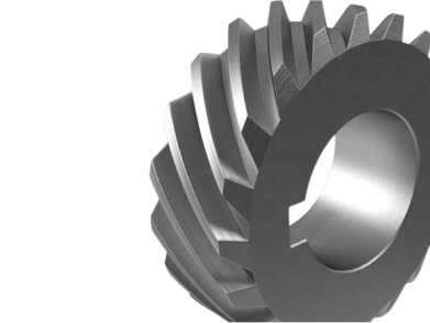
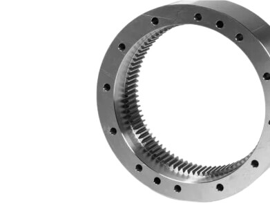
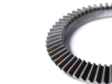
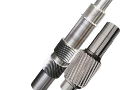
Worm Gear Set Description
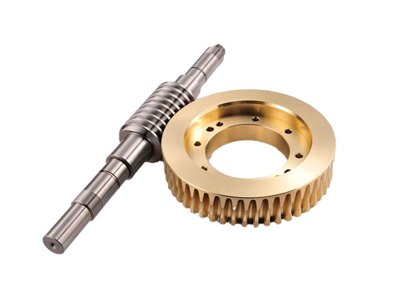
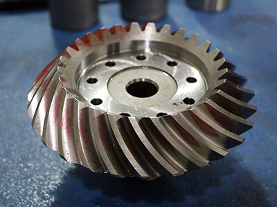
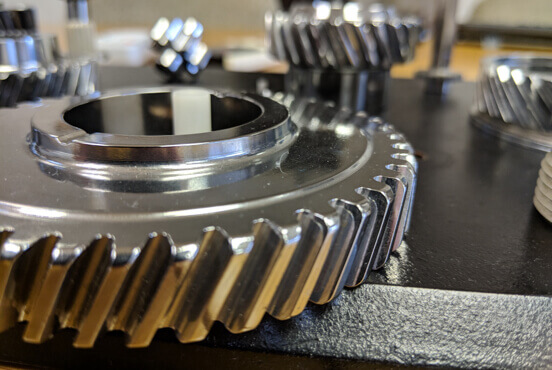
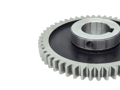
A worm gear set is a unique type of gear arrangement that consists of two primary components: a worm, which is a screw-like gear, and a worm wheel (or worm gear), which is a gear that meshes with the worm. This configuration allows for significant reductions in speed and increases in torque, making worm gear sets invaluable in applications where high torque and low speed are required. The design is particularly effective in transmitting power between non-parallel shafts, typically at right angles, making it a versatile choice for various mechanical systems.
Due to the compact design, worm gear reducers are able to be placed in relatively small spaces and provide high-ratio speed reduction.. This is accomplished through the sliding contact between the worm and the worm wheel, which not only allows for smooth operation but also leads to self-locking behavior in many designs. Self-locking ensures that the output shaft cannot backdrive the input shaft, providing an additional layer of safety in applications.
Applications
Automotive
Used in steering mechanisms and gear shifters.
Conveyors
Employed in conveyor systems to control movement.
Industrial Equipment
Common in hoists, lifts, and other machinery requiring high torque at low speeds.
Aerospace
Utilized in certain mechanisms where precise motion control is essential.
Manufacturing Method of Worm Gear Set
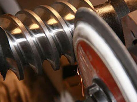
Gear Hobbing
Description: A gear cutting process that uses a hob (a specialized cutting tool) to shape the gear teeth.
Advantages: Suitable for high-volume production; efficient and cost-effective for manufacturing gears with complex tooth profiles.
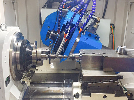
Gear Milling
Description: Uses a milling machine to cut the gear teeth. This method is often used for smaller gears or specialized shapes.
Advantages: Versatility in producing different gear types and sizes; can be used for both prototype and production runs.
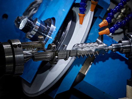
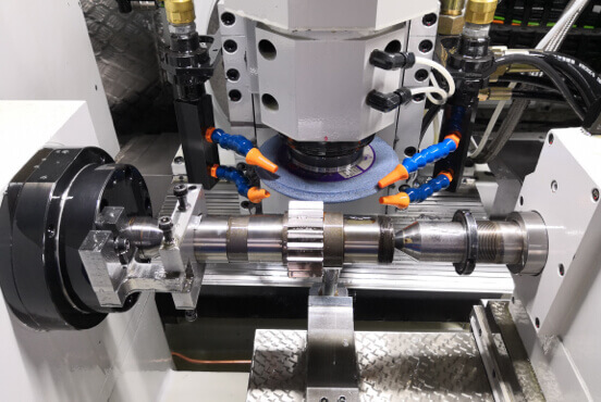
Gear Grinding
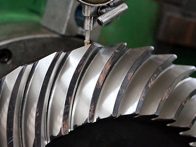
Description: Involves using a grinding wheel to refine the tooth profile and achieve precise dimensions and surface finishes.
Advantages: Provides high accuracy and smooth surface finishes; often used as a secondary process after hobbing or shaping.
Common Steel Code
Grades Comparison
| CHINA/GB | ISO | ГΟСТ | ASTM | JIS | DIN |
| 45 | C45E4 | 45 | 1045 | S45C | CK45 |
| 40Cr | 41Cr4 | 40X | 5140 | SCr440 | 41Cr4 |
| 20CrMo | 18CrMo4 | 20ХМ | 4118 | SCM22 | 25CrMo4 |
| 42CrMo | 42CrMo4 | 38XM | 4140 | SCM440 | 42CrMo4 |
| 20CrMnTi | 18XГT | SMK22 | |||
| 20Cr2Ni4 | 20X2H4A | ||||
| 20CrNiMo | 20CrNiMo2 | 20XHM | 8720 | SNCM220 | 21NiCrMo2 |
| 40CrNiMoA | 40XH2MA/40XHMA | 4340 | SNCM439 | 40NiCrMo6/36NiCrMo4 | |
| 20CrNi2Mo | 20NiCrMo7 | 20XH2MA | 4320 | SNCM420 | |
| 17CrNiMo6 | |||||
| 18CrNiMo7 | |||||
| ZCuSn10P1 |
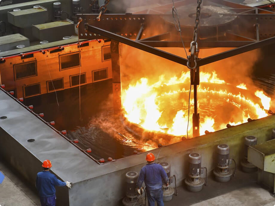
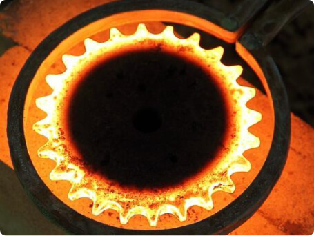
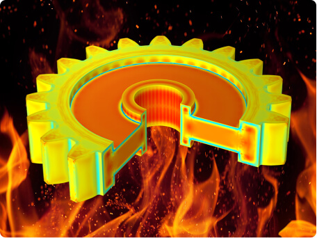
Common Heat Treatment Process
Heat treatment is a controlled process used to alter the physical and sometimes chemical properties of materials, particularly metals. It can enhance properties such as hardness, strength, toughness, and ductility. Here are some common heat treatment processes:
01
Annealing
Purpose
To soften the material, improve ductility, and relieve internal stresses.
Process
Heating the metal to a specific temperature and then cooling it slowly, usually in air or in a furnace.
02
Quenching
Purpose
To increase hardness and strength.
Process
Heating the metal to a high temperature and then rapidly cooling it in water, oil, or air. This process can induce stresses in the material.
03
Tempering
Purpose
To reduce brittleness after quenching and improve toughness.
Process
Heating the quenched metal to a lower temperature (below its critical point) and then cooling it, allows for some of the internal stresses to be relieved.
04
Normalizing
Purpose
To refine the grain structure and enhance mechanical properties.
Process
Heating the steel above its critical temperature and allowing it to cool in air. This results in a uniform microstructure.
05
Hardening
Purpose
To increase hardness and wear resistance.
Process
Involves quenching, followed by tempering to achieve desired hardness levels, commonly applied to tool steels.
06
Case Hardening
Purpose
To harden the surface of a material while maintaining a softer, ductile core.
Process
Methods include carburizing (adding carbon) or nitriding (adding nitrogen) to the surface layer, followed by quenching.
Manufacturing Capacity of Worm Gear Set
| Item | Description |
| Gear Type | Worm Gear Set |
| Module (m) | Max 25 |
| DP | 0.75 |
| Pressure angle (α) | 20 Deg/14.5 Deg |
| Helix angle (β) | Max 35 Deg |
| Number of teeth (z) | |
| Facewidth (b) | 800mm |
| Profile shift coefficient (x) | Customized |
| Face width (b) | Customized |
| Tip diameter (da) | Max 3 Meter |
Quality Control of Worm Gear Set
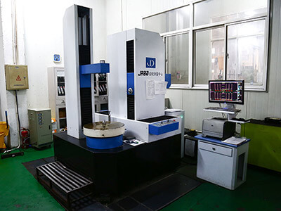
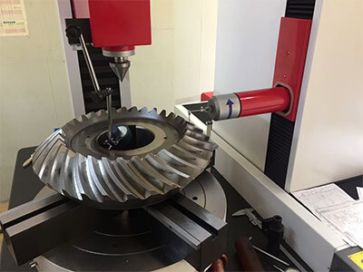
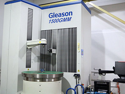
Quality control is essential in the manufacturing of spur gears to ensure they meet specified standards and function effectively in their applications. The following are key aspects and methods used in the quality control process for spur gears:

